The Termite
The Termite Core Drill
Description/Construction | Control Panel Functions | Technical Specifications
Designed by Swedish engineers, the Termite Core Drill offers lightweight, modular hydraulically powered solutions for short-hole exploration, definition and grout hole drilling. The Termite Core Drill has a straight forward, clean design that demands few spare parts, making it the most reliable core drill of its kind on the market.
The Termite Hydraulic Core Drill is supplied by state-of-the-art hydraulic components. Equipped with a reliable rotation unit that is driven by a high-tech belt drive, The Termite Core Drill offers the best solution for consistent drilling and accuracy. Our drill is an optimal choice for hole depths up to 100 meters (300 feet).
Not limited to the mining industry, the Termite Core Drill is also designed for construction core drilling purposes with large and small thin-wall diamond bits, as well as for use in the dimensional stone industry for precision drilling of wire cutting holes, and to check on the quarry’s material quality.
The total weight of the Termite Core Drill and control panel is only 160 kg (350 lbs.), making it easy to maneuver to and from any site.
Advantages of choosing the Termite:
- Affordability
- Few spare parts
- Simple design for quick maintenance (no special tools or technicians are needed to repair)
- Ease of operation (avoid expensive contractors: do the core drilling yourself)
The Termite Hydraulic Core Drill can be powered with:
- Tractor PTO
- Bobcat or similar skid steer machines by utilizing their on board hydraulic system
- Diesel or gas power unit
- Electric power unit
Description / Construction
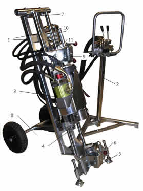 The drill frame is constructed out of two hydraulic feed cylinders and two square tubes (1). These are connected at both ends by the connection plates. The front connection plate is also designed to hold the front rod puller (5) and the two mounting screws (6). The mounting tube(7) for the back support leg is located on the rear connection plate.
The drive spindle (4) and hydraulic motor(3) are mounted on the carrier plate that swings out to let rods or core barrels in or out of the hole without having to pass through the chuck. Also on the back end of this carrier plate is a mounting for the rear rod puller (9). The power to the spindle from the hydraulic motor is transmitted via belt drive; a very effective, smooth, low maintenance, and quiet power transmission system.
The drill is operated from a separate control panel (2). The control panel can be separated from the drill by disconnecting it at the bulkhead (10). A separate small hydraulic pump is mounted on the back end of the rotation motor. This unit supplies the hydraulics needed for the drill feed. The feed speed is regulated at the exit of the cylinders. Because of this configuration, feed pressure and feed speed are unaffected by the prevailing system pressure. Therefore, the speed will not change when drilling into a void or into an opening.
Two removable wheels (8) are mounted on the bottom of the frame for easy transportation. A support (11) for rod wrenches is located on the carrier; this protects the piston rods when breaking rod connections with wrenches.
Control Panel Functions
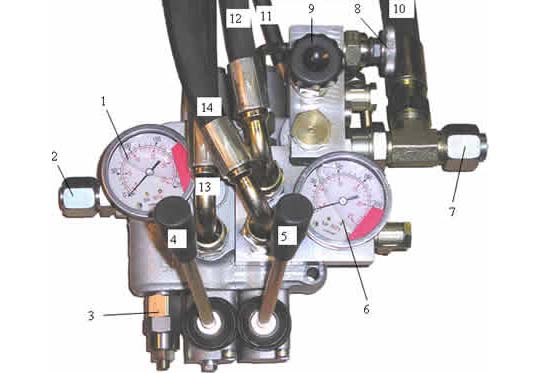
- System Pressure Gauge
(maximum pressure 180 Bar) - Pressure connection from Power Unit
- Pressure Relief Valve, System pressure
- Operations Handle for rotation
Only right-hand rotation is possible - Operations Handle for rod running and fast feed
- Feed Pressure Gauge
- Return oil connection back to Power Unit
- Knob for adjustment of feed speed
- Knob for adjustment of feed pressure
- Return Hose from Rotation Motor, via Bulkhead
- Pressure Hose from Feed Pump, via Bulkhead
- Hose to Feed Cylinder Block, upper connection, via Bulkhead
- Pressure Hose to Rotation Motor, via Bulkhead
- Hose to Feed Cylinder Block, lower connection, via Bulkhead
Drill feed will work only when the spindle rotates. When setting the feed pressure, knob #8 must be fully closed. The desired maximum feed pressure can then be adjusted with knob #9. 100 bar pressure equals approximately 2200 lbs. of feed force. With knob #8, the desired feed speed can now be adjusted. The pressure reading on Gauge #6 will change while drilling, depending on the feed speed setting on Knob #8. When the pressure on Gauge #6 shows zero while drilling, at that time the feed is working at the full preset pressure.
Technical Specifications
| @ 50 liters/minute, 180 bar | ||
|---|---|---|
| Max. Feed Force | 20 kN | Approx. 4400 lbs |
| Max. Pull Force | 18 kN | Approx. 4000 lbs |
| Revolutions | 1450 rpm | |
| Rod Running Speed | 1.7 m/sec | Approx. 4.6 ft/sec |
| Max. Feed Speed | 1.3 m/min | Approx. 3.3 ft/min |
| Stroke | 0.5 m | Approx. 20 in. |
| Power | 15 kW | Approx. 20 hp |